
Few years ago, my GE refrigerator (Model # PFCF1NFWA) stopped cooling after a power outage.
Fast forward to today and after a 6 hour power outage, the same refrigerator stopped cooling again!
In addition to showing you how to troubleshoot and fix this problem, I am also going to share how to minimize the risk of this happening again in the future.
SYMPTOMS
After getting the power back, my refrigerator seemed to work for about 12 hours but then stopped generating cool air.
Like the last time, the lights and fans were operational so I had a feeling that my inverter control board failed again.
REQUIRED TOOLS
- 3/8″ socket
- Mini socket ratchet
- Screwdriver (flat / Phillips)
- Can of compressed air (do not use your pancake compressor!!)
- Vacuum
- Digital Multimeter or DMM (1)
- Some foil / duct tape
(1) Please note that you will need a multi-meter for this project. And don’t worry. Using a multimeter is not as complicated as it sounds and I will show you exactly how to use it in this article.
REQUIRED PARTS
Because I have done this test/repair on m refrigerator before, I am confident that I need a replacement inverter control board. You should first go through the entire testing steps below before making a purchase.
TESTING STRATEGY
The overall troubleshooting strategy is to:
- First, leverage the refrigerator’s internal diagnostic tools to check the thermistors;
- Second, test the central motherboard;
- Third, test the compressor leads to indirectly verify the inverter controller board
SETTING UP THE DIGITAL MULTIMETER
Exact steps outlined here may vary slightly but most DMMs have the setup so it should not be a problem if you have a different DMM than mine (Klein MM2300).
- Step # 1 – For testing J15 jumpers, we will be using probes leads.
- Step # a – Turn on the unit by placing the center twist lock to “V”;
- Step # b – Insert the black “banana” side of the probe into the “COM” port;
- Step # c – Insert the red “banana” side of the probe into the port labeled “V” (it may have other labels like Ohm, Temp, etc);
- Step # d – Prior to each readouts, make sure to touch the metal part of the black and red test leads and cthe DMM reads “0” (zero). This step is a MUST to obtain accurate readings;
- Step # 2 – For measuring resistance (Ohm) on 3 compressor posts, we will be using the alligator clips;
- Step # a – Turn on the unit by placing the center twist lock to “Ohm” (label looks like a girls head);
- Step # b – Insert the black “banana” side of the alligator clip into the “COM” port;
- Step # c – Insert the red “banana” side of the alligator clip into the port labeled “V” (it may have other labels like Ohm, Temp, etc);
- Step # d – Prior to each readouts, make sure to touch the metal part of the black and red test leads and cthe DMM reads “0” (zero). This step is a MUST to obtain accurate readings;
TROUBLESHOOTING STEPS
- Step # 1 – Utilize the refrigerator’s self-diagnostic tool to verify that all sensors (thermistors) are in working order. I have outlined the exact steps in my previous post, How to Use Built-in Control Diagnostics. Once verified, return to this post;
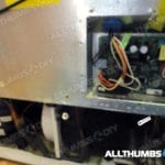
- Step # 2 – Slide out the refrigerator to gain access to the rear side;
- Step # 3 – Remove the main motherboard (metal) cover and the bottom cardboard cover; Touch any part of the rear refrigerator metal frame to eliminate any static electricity;
-
-
-
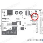
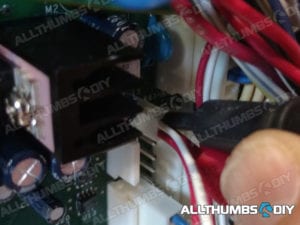
- Step # 4 – Insert the black and red test probes into the J15 jumper connector with the wiring in place. It does not matter which colored probes goes where. Leave the connector in place to test for several reasons:
- J15 leads are very close to each other so you may end up touching test leads with each other, making the readout useless
- J15 leads are fairly fragile so they are easy to bend/break. If you break one of them, you may have to desolder/solder on a new one (good luck with that one) or buy a new motherboard ($160 bucks!!);
-
-
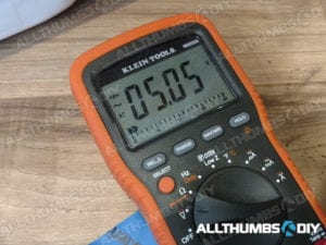
- Step # 5 – The manual states that you should get anywhere between 4 to 10 volts. Mine came in at 5.05 so the main motherboard is in good working order;
- Step # 5b – Unplug the refrigerator
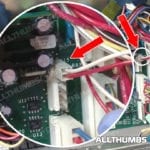
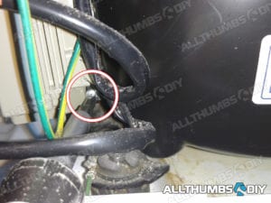
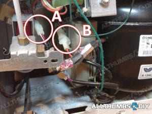
- Step # 6 – Disconnect two wires near the compressor as shown; To disconnect “A”, simply press down on the flat side and gently separate the two plastic connectors. To disconnect “B”, pinch or squeeze the side clips then gently pry them off from each other;
- Step # 7 – Using a Phillips screwdriver, locate and remove the bottom screw on the inverter control board unit;
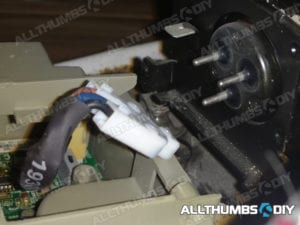
- Step # 8 – Gently tip the inverter unit to the left and expose the white connector that is attached to the compressor;
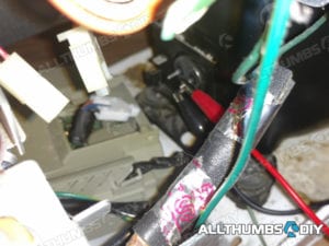
- Step # 9 – Gently pry off the connector which will expose 3 metal posts on the compressor;
-
-
- Step # 10 – Remove the inverter control board, being careful of the surrounding wires and pipes. It seems tight but take your time and experiment by rotating the unit. It will come out;
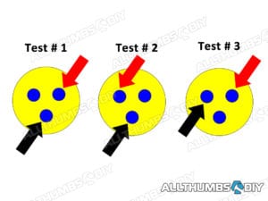
- Step # 11 – Now we need to take resistance (not voltage) readings so turn the twist lock on the DMM to “Ohm”. Using alligator clips, test two posts at a time; use the following patterns which will result in 3 readouts;
- Step # 12 – Each pair of posts averaged out to be 6.6 Ohm (well within 6-8 Ohm as stated in the manual) so the compressor was in working order;
-
-
- Step # 13 – By process of elimination, the middle component between the main motherboard and the compressor is the only remaining culprit (test was set up this way because there is no easy way to directly test the inverter board)
If the reading is still not in the proper range, you will have to replace the compressor and the refrigerant. I am afraid this is NOT a DIY project and you will have to call in a technician
REPLACEMENT STEPS
When I received the replacement part # WR49X10283, I noticed right away that GE had made some enhancements and/or modifications:
- Exterior – The shell is now black and has a large metal shield. The size is about the same;
- Extra Grounding Wire – In addition to the normal grounding wire that is attached to the refrigerator’s metal frame, another wire is connected from the board to the metal shield;
- Specifications – Specifications are virtually identical, EXCEPT the voltage output was reduced from 230V-53 to 150Hz to 230V-53 to 133 Hz
My last replacement purchased few years was a verbatim copy of the inverter board that came with the refrigerator so I am hoping that all these latest changes will make the inverter board last longer this time.
CONCLUSION
I believe the inverter control board is one of the hardest working components.
By design, it is working almost 24×7 and it has to control the compressor via Pulse Width Modulation (PWM), which means it sends effective voltages between 80 and 230 VAC to the compressor.
It is not uncommon to find one or more blown capacitors on this board due to its harsh working environment.
Mix that with inevitable electrical spikes and surges during power restoration, it makes perfect sense why inverter control board is the first to go.
To minimize the risk of repeating this event, I am going to purchase a high quality, heavy-duty power surge protector specifically designed for the refrigerator.

PS. If you found this article to be useful, why not sign up for my newsletter? Just look for a signup form on the upper right hand side of your screen. Thanks!
Warren
Tuesday 4th of July 2023
It sounds like one takeaway is that an inverter refrigerator isn't the best choice for areas with poor quality power (frequent brownouts, blackouts, and spikes). Correct?
Asking because I'm shopping for a new refrigerator. The (non inverter) refrigerator to be replaced has put up with our poor quality power for 20 years with only one compressor replacement, and I prioritize robustness over energy savings.
Maintaining a GE Profile PFCF1NFW Refrigerator — AllThumbsDIY.com
Saturday 27th of February 2021
[…] Step # 8 – Gently wipe down the compressor with a moist rag; using a can of compressed air, gently blow off any hair or debris around the inverter; then examine the inverter with a flashlight to detect any discoloration or cracks; once a year, the inverter casing is NOT completely enclosed so once a year, I remove the inverter to examine the innards (to learn about removing a inverter, read my post “How to Fix a GE Profile Refrigerator that is Not Cooling Again“ […]
Adam
Thursday 26th of November 2020
My j15 came in at 11.88 V. I did direct check the board with jumper disconnected. this was while the inverter box was out of the fridge. thought my box may be bad but now i am concerned that its the main board. haven't found link to self diagnostic, so don't know my codes, but the compressor checks good but does not turn on. all else appears fine.
Repairing Articulating Mullion Assembly on GE Profile refrigerator — AllThumbsDIY.com
Saturday 21st of November 2020
[…] you have read my other posts, I’ve had to replace very expensive inverter boards three times (How to Fix a GE Profile Refrigerator that is Not Cooling (Ugh, Again) ) but I feel that even with those expenses factored in, the refrigerator has been good to my […]
Ed
Monday 4th of February 2019
Hi again Kevin,
Thanks for getting back to me so quickly, and for clarifying about the J15 voltage test. And yes, that resin is exactly what I'm seeing. I understand there were some issues with the original inverters supplied with these fridges, so I'm glad GE has made changes to try to resolve them.
I'm off to replace my inverter.
Thanks again!
Ed