

Key Points
- Thermistors provide critical temperature data to the main control board which in turn governs the refrigerator operation
- Learn how to visually inspect, perform tests and if necessary replace faulty thermistors temperature sensors
- All thermistors used in GE refrigerators are identical with part #WR55X10025. You can check the latest price here
- Plan on testing/replacing the defrost thermostat at the same time
| TIPS |
|---|
| Although this section as intended for a GE Profile PFCF1NFW refrigerator, many information will be applicable to other GE refrigerators made after after 2006. |
Table of Contents
- Background Info
- Visual Inspection
- How to Test a Thermistor
- Positive Temperature Coefficient (PTC) – resistance value increases as the temperature increases
- Negative Temperature Coefficient (NTC) – resistance value decreases as the temperature increases (i.e. inversely proportional)
- Fresh food thermistor – located in the fresh food compartment (upper left wall, covered with a fish fill cover plate). It provides temperature data in the “fridge” or fresh food (ff) compartment to the main control board that will determine if a damper should be opened or closed to increase/decrease cold air flow into the FF compartment
- Freezer thermistor – located in the FZ compartment (right wall, covered with a fish fill cover plate), it provides temperature data for the freezer (fz) compartment. This data is used to either ramp up or slow down the compressor and/or condenser fan. The main control board can also elect to shutdown the compressor and/or condenser but continue to operate the variable speed evaporator fan.
- Ambient thermistor – located behind the toe kick plate (bottom of the refrigerator), it provides “ambient” or kitchen (or garage) room temperature (not inside of a refrigerator). This information is used in conjunction with FF and FZ thermistors to calculate the cooling requirement. If the ambient thermistor is not functioning properly, the main control board will default and assume the ambient temperature is 90 F and will NOT make any adjustment to the fresh food or freezer set point.
- Evaporator thermistor – located in the freezer compartment clipped on to the suction tube of the evaporator. This particular thermistor acts as the primary detector (defrost temperature sensor acts as a backup) to see if defrosting cycle needs to be turned on
- Fridge too warm / freezer cold
- Fridge / Freezer too warm
- Defrosting cycle does not work (i.e. ice build up on the evaporator)
- Displayed temperature is not accurate
- Excessive cooling outside set parameter
- Erratic/fluctuating temperatures throughout the day
- Non-destructive, Passive testing from the main control board (ohm meter function)
- Advantages – quick / minimal amount of work
- Disadvantages – cannot test thermistor located on the evaporator suction tube
- Non-destructive, Active testing from the main control board (voltage meter function)
- Advantages – quick / minimal amount of work
- Disadvantages – cannot test thermistor located on the evaporator suction tube
- Destructive testing from each location
- Advantages – evaporator thermistor can be tested in a controlled environment
- Disadvantages – requires cutting and re-splicing wires
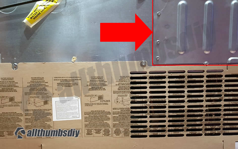
- Step # 1 – pull out the refrigerator to gain access to the rear panel
- Step # 2 – using 3/8″ socket, remove screws from the cover to expose the main control board
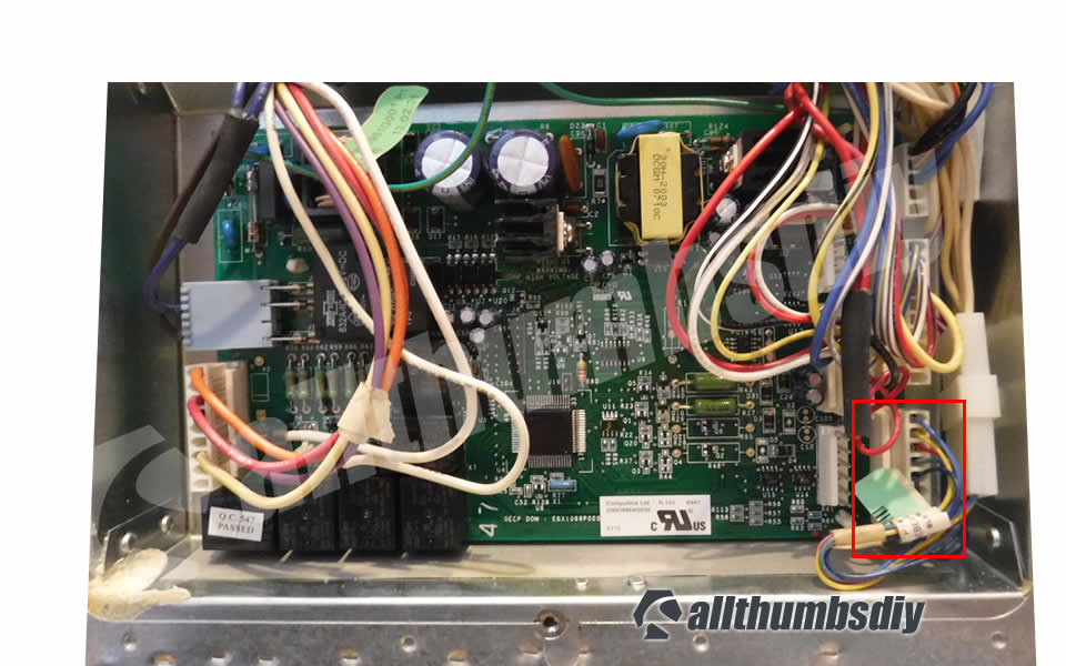
- Step # 3 – Touch any part of the rear metal panel (but not near the main control board) to discharge static electricity from your body
- Step # 4 – Multi-meter comes with red and black test leads; since we are not testing for polarity, it does not matter which lead goes to terminals
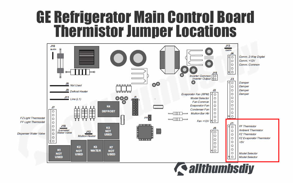
- Step # 5 – There are five pins at the J1 jumper on the main control board
- Pin 1 – Fresh Food Thermistor (blue wire)
- Pin 2 – Ambient Thermistor (yellow wire)
- Pin 3 – Freezer Thermistor (red wire)
- Pin 4 – Evaporator Thermistor (green wire)
- Pin 5 – Thermistor Voltage Supply (+5 VDC)
- Step # 6 – Remove the FF thermistor fish gill cover (located on the upper left wall in the fridge compartment and gently pull out the thermistor
- Step # 7 – Submerge the thermistor in a small zip-loc bag and duct tape to the wall with ice and a small amount of water for 5 minutes (will approximately simulate 32 degrees in Fahrenheit)
- Step # 8 – Remove the wire retention wire harness clip at the main control board
- Step # 9 – Insert the red lead from a multimeter into the pin 1 on the retention wire harness clip (not the main control board)
- Step # 10 – Insert the black lead from a multimeter into the pin 5 on the retention wire harness clip (not the main control board)
- Step # 11 – Take an OHM reading from your multimeter; it should be around 16.3 Kilo-Ohms (16,300 Ohms). Any reading that is more or less than 5% from this value means your thermistor is bad and will need to be replaced.
- Step # 6 – Remove the FZ thermistor fish gill cover (located on the right wall in the freezer compartment) and gently pull out the thermistor
- Step # 7 – Submerge the thermistor in a small glass (or small zip-loc bag and duct tape on the wall) with ice and small amount of water for 5 minutes (will approximately simulate 32 degrees in Fahrenheit)
- Step # 8 – Remove the wire retention wire harness clip
- Step # 8 – Insert the red lead from a multimeter into the pin 3 on the retention wire harness clip (not the main control board)
- Step # 9 – Insert the black lead from a multimeter into the pin 5 on the retention wire harness clip (not the main control board)
- Step # 10 – Take an OHM reading from your multimeter; it should be around 16.3 Kilo-Ohms (16,300 Ohms). Any reading that is more or less than 5% from this value means your thermistor is bad and will need to be replaced.
- Step # 6 – Remove 2 screws holding down the toe kick panel, put aside the panel; cut off the zip tie holding down the thermistor
- Step # 7 – Submerge the thermistor in a small zip-loc bag with ice and small amount of water for 5 minutes (will approximately simulate 32 degrees in Fahrenheit)
- Step # 8 – Remove the wire retention wire harness clip
- Step # 8 – Insert the red lead from a multimeter into the pin 2 on the retention wire harness clip (not the main control board)
- Step # 9 – Insert the black lead from a multimeter into the pin 5 on the retention wire harness clip (not the main control board)
- Step # 10 – Take an OHM reading from your multimeter; it should be around 16.3 Kilo-Ohms (16,300 Ohms). Any reading that is more or less than 5% from this value means your thermistor is bad and will need to be replaced.
- Step # 6 – Remove the FF thermistor fish gill cover (located on the upper left wall in the fridge compartment and gently pull out the thermistor
- Step # 7 – Submerge the thermistor in a small zip-loc bag and duct tape to the wall with ice and a small amount of water for 5 minutes (will approximately simulate 32 degrees in Fahrenheit)
- Step # 8 – Remove the wire retention wire harness clip at the main control board
- Step # 9 – Insert the red lead from a multimeter into the pin 1 on the retention wire harness clip (not the main control board)
- Step # 10 – Insert the black lead from a multimeter into the pin 5 post on the main control board
- Step # 11 – Take a voltage drop reading from your multimeter:
- 0 VDC = defective; circuit shorted out; replace
- 0-1 VDC = possibly defective; replace
- 1 to 4 DC volts = acceptable
- 4-5 VDC = possibly defective; replace
- >5 VDC = open circuit (i.e. infinite resistance); replace
- Step # 6 – Remove the FZ thermistor fish gill cover (located on the right wall in the freezer compartment) and gently pull out the thermistor
- Step # 7 – Submerge the thermistor in a small glass (or small zip-loc bag and duct tape on the wall) with ice and small amount of water for 5 minutes (will approximately simulate 32 degrees in Fahrenheit)
- Step # 8 – Remove the wire retention wire harness clip
- Step # 9 – Insert the red lead from a multimeter into the pin 3 on the retention wire harness clip (not the main control board)
- Step # 10 – Insert the black lead from a multimeter into the pin 5 on the main control board
- Step # 11 – Take a voltage drop reading from your multimeter:
- 0 VDC = defective; circuit shorted out; replace
- 0-1 VDC = possibly defective; replace
- 1 to 4 DC volts = acceptable
- 4-5 VDC = possibly defective; replace
- >5 VDC = open circuit (i.e. infinite resistance); replace
- Step # 6 – Remove 2 screws holding down the toe kick panel, put aside the panel; cut off the zip tie holding down the thermistor
- Step # 7 – Submerge the thermistor in a small zip-loc bag with ice and small amount of water for 5 minutes (will approximately simulate 32 degrees in Fahrenheit)
- Step # 8 – Remove the wire retention wire harness clip
- Step # 9 – Insert the red lead from a multimeter into the pin 2 on the retention wire harness clip (not the main control board)
- Step # 10 – Insert the black lead from a multimeter into the pin 5 on the main control board
- Step # 11 – Take a voltage drop reading from your multimeter:
- 0 VDC = defective; circuit shorted out; replace
- 0-1 VDC = possibly defective; replace
- 1 to 4 DC volts = acceptable
- 4-5 VDC = possibly defective; replace
- >5 VDC = open circuit (i.e. infinite resistance); replace
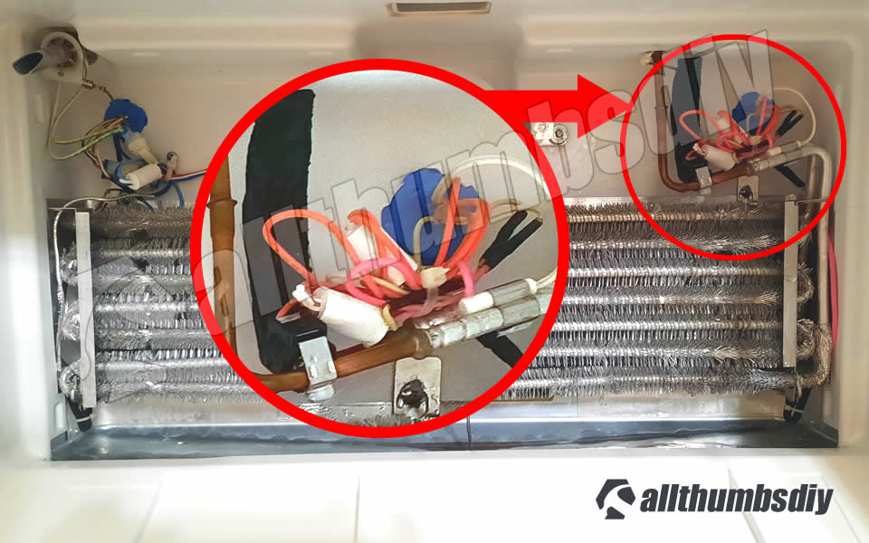
- Evaporator thermistor is bundled together with other wires, tucked into the upper right hand corner behind the evaporator cover
- Because it is in a tight confined space and lots of parts need to be removed to gain access, I highly recommend that you skip the test and go right to replacing both the evaporator thermistor and defrost heater thermostat at the same time (unless they have recently been replaced)
- This defrost termination thermostat (Defrost Limiter Thermostat, High Limit Thermostat, Refrigerator Defrost Bi-Metal Thermostat) acts as a safety device to stop the evaporator coil from overheating, by turning off the defrost heater at the end of the defrost cycle. This part attaches to the tubing of the evaporator coil in the freezer.
- A faulty defrost termination thermostat may result in the defrost heater never heating and a solid frost buildup on the evaporator coil, which results in too warm temperatures. The thermostat contacts are normally closed and have continuity until it reaches 140 degrees. If this high limit thermostat is open at room temperature or colder, it is defective. This limit thermostat has an attached mounting clip and comes with pink and amber wire leads. The thermostat is 1 inch in diameter and 1/2 inch thick, the 2 wire leads are 10 inches long.
- Thermistors (external link, Wikipedia)
- Thermistors and NTC Thermistors(external link does not allow direct linking; please copy and paste; )
- Temperature Sensors (external link does not allow direct linking; please copy and paste; https://www.electronics-tutorials.ws/io/thermistors.html)
- Sintered Metal Oxide for Thermistor (external link, US Patents-Google)
Background Info
A thermistor, which is combination of the words thermal and resistor, is a type of resistor used to measure temperature changes and deliver differing electrical resistance in response to that change. Because thermistors are highly sensitive in order to maintain temperature for refrigerators, it is vital to ensure that thermistors are working correctly 24/7.
Please note that there are two types of thermistors:
Thermistors used in GE refrigerators are made up of NTC (sintered metal oxides ceramic made of manganese, nickel, cobalt and other elements), combined with binders and stabilizers then pressed into a precise shape to dictate their resistance and temperature curve.
The main control board provides an excitation voltage (+5v) to the thermistor with a 2-wire connection (this is because the thermistor change in resistance is large compared to the resistance of the leads).
The excitation is then converted to a voltage signal by the thermistor and the main control board converts the measured voltage to temperature.
| Temperature (Fahrenheit) | Temperature (Celsius) | Resistance (Kilo-Ohms) |
|---|---|---|
| -40 | -40 | 166.8 |
| -31 | -35 | 120.5 |
| -22 | -30 | 88 |
| -13 | -25 | 65 |
| -4 | -20 | 48.4 |
| 5 | -15 | 36.4 |
| 14 | -10 | 27.6 |
| 23 | -5 | 21 |
| 32 | 0 | 16.3 |
| 41 | 5 | 12.7 |
| 50 | 10 | 10 |
| 59 | 15 | 7.8 |
| 68 | 20 | 6.2 |
| 77 | 25 | 5 |
| 86 | 30 | 4 |
| 95 | 35 | 3.2 |
| 104 | 40 | 2.6 |
| 113 | 45 | 2.2 |
| 122 | 50 | 1.8 |
| 131 | 55 | 1.5 |
| 140 | 60 | 1.2 |
On the other hand, defrost thermostat is a less technologically advanced device consisting of bi-metals (often made of copper and aluminum) to open or close its circuit based on temperature changes.
Keystone (Thermometrics) vs EPCOS Thermistors
Around 2010, GE discontinued using thermistors made by Keystone/Thermometrics under the General Electric Information Services (GEIS) label due to high failure rate caused by moisture penetration. Keystone/Thermometrics thermistors have an open bottom (usually in black) at the point of wire entry into the polymer casing. This casing will also have a distinct “dome”.
Since then, all GE refrigerators (not just PFCF1NFW model) contain EPCOS thermistors which have conductors embedded in a sealed, flat-top design in white polymer shells.
Regardless of a particular design, any color discoloration, cracking or bulging would indicate a problem with the thermistor and it will need to be replaced.
Iif you happen to find Keystone/Thermometrics thermistors, plan on replacing with the EPCO thermistors as a precaution. All GE refrigerators use EPCOS thermistors (part number #WR55X10025)
Thermistor Location
There are four thermistors located in a GE Profile PFCF1NFW refrigerator:
Defrost Thermostat Location
Defrost thermostat is located in the freezer compartment, usually clipped tightly on to a tubing attached to the evaporator.
In many cases, a defrost thermostat is found next to the evaporator thermistor and to gain access, you will need to remove many parts out of the way (door, shelves, panels).
Thermistor/Defrost Thermostat Failure Symptoms
Here are some obvious symptoms of a failing thermistor:
What Causes Thermistors to Fail
Thermistors rarely, if ever, fail completely (which would make our job very easy), although we sometimes see a thermistor fail due to an open circuit resulting from a break in wires between the thermistor and main control board. This usually happens when wires are spliced incorrectly allowing moisture penetration.
The most common reason why thermistors fail is simply aging. Over time, sintered non-oxides in thermistors lose its efficiency and provides signals that are no longer accurate.
Can You Tell a Failing Thermistor By Visual Inspection?
Obvious color discoloration, cracking or bulging would be great to quickly solve a malfunctioning refrigerator but unfortunately, most failures involve internal chemical degradation in resistance over a period of time. That means you CANNOT rely only on a visual inspection to detect your problem.
Instead, you should TEST each thermistors using a multimeter (see next section).
Using Self -Diagnostics to Test for the Thermistors?
Not if you value your time.
You certainly can run the self-diagnostics but this test can only detect a closed or open circuit and thermistors normally do not fail this way. Instead, sintered non-oxides in thermistors lose its potency and lose their ability to provide correct resistance.
How To Test a Thermistor
You will need a multimeter to perform these tests. If you need one, read my post How to buy a Multimeter article.
Please remember that thermistors are a VDC component so a shorted thermistor will shut down the entire refrigerator.
It can also deviate from their normal value or resistance at any given temperature, resulting in “too warm” or “roo cold” complaints.
There are three ways to test a thermistor:
Destructive testing method requires cutting off thermistors, test them and re-installing them back into original place. Removing thermistors make it easy to test (especially for the evaporator thermistor that is in a very tight space), BUT splicing wires back will be difficult because existing wires are very short.
Thus we will only review the non-destructive (active and passive) testing method in this post.
| Evaporator Thermistor and Defrost Temperature Sensor |
|---|
| Unless the evaporator thermistor and defrost temperature sensor have been replaced recently, I highly recommend skipping the test for these two sensors and just replace both of them. |
Non-destructive Testing
For this method, you will be testing the resistance from the opposite end of a thermistor that terminates at the main control board. Passive testing method will simply measure the resistance; active testing method will measure the excitation voltage (more accurate) across a thermistor.
Please note that both leads from the multimeter will be touching the wires from the sensors. Another words, multimeter test leads should NOT be touching the pins on the main control board.
Passive Testing Method
You will need to unplug the refrigerator before starting this test. Set your multi-meter to ohm.
Test the Fresh food (FF) Thermistor
Test the Freezer (FZ) Thermistor
Test the Ambient Thermistor
Active Testing Method
You will need to leave your refrigerator plugged in for this test to measure voltage drop across thermistors.
| WARNING |
|---|
| Please be careful as you can easily damage the main control board by accidentally touching other parts! |
Set your multimeter to voltage meter.
Test the Fresh food (FF) Thermistor
Test the Freezer (FZ) Thermistor
Test the Ambient Thermistor
Test the Evaporator Thermistor (a.k.a. defrost sensor)
Test the Defrost thermostat
Defrost thermostat in GE refrigerators are secondary back up to thermistors so they rarely fail.
If your refrigerator is not cooling properly, I would replace it (costs under $20) along with the evaporator thermistor . Please refer to the diagram # 266 in my parts page for the latest part # and price.
How to Replace a Thermistor or Defrost Thermostat
Should you need to replace a thermistor, use plastic bell connector (part # WR01X10466) to splice the wires and fill each connector with RTC102 silicone to prevent water penetration.

Key Takeaways
It can be very stressful and confusing to troubleshoot a non-working refrigerator, especially with many automated features like digital temperature maintenance and auto-defrost.
However, most problems can be solved if you triage the problem and each components.
Good luck with your project!

Carlos A N Botelho
Wednesday 2nd of November 2022
Hi... Thank you very much for the information about possible faults and repairs for my GE side-by-side refrigerator. I've done every step, checked every point but my refrigerator keeps running longer than it should. There is no ice formation in the evaporator and the fan is operating normally at high speed. A question, when I press the button on the panel, it happens that, on the first touch, it shows high temperatures (27/44) after two hours of operation. These numbers are decreasing, but the compressor does not stop working. should i wait 24 hours to rate better? Is there any other procedure to be done? I'm not a refrigeration technician but I know electronics and electricity. I'm like DIY. Thanks. PS) I'm Brazilian and I'm in Brazil.
Carlos A. N. Botelho
Wednesday 2nd of November 2022
Hi... Thank you very much for the information about possible faults and repairs for my GE side-by-side refrigerator. I've done every step, checked every point but my refrigerator keeps running longer than it should. There is no ice formation in the evaporator and the fan is operating normally at high speed. A question, when I press the button on the panel, it happens that, on the first touch, it shows high temperatures (27/44) after two hours of operation. These numbers are decreasing, but the compressor does not stop working. should i wait 24 hours to rate better? Is there any other procedure to be done? I'm not a refrigeration technician but I know electronics and electricity. I'm like DIY. Thanks. PS) I'm Brazilian and I'm in Brazil.
Malcolm
Thursday 3rd of June 2021
My under-counter freezer cools down well consuming about 60w. Eventually (I assume when the temperature is cold enough) measured this to below -20deg C, the power consumption decreases to about half this amount and it slowly warms to about 0deg C. I cannot get it to cool anymore, switch off and on again will not start cooling, nor will decreasing the thermostat.
The only way to get freezing to work is to leave it off for several hours, switch on and it repeats the above process.
It has a PSC motor. The capacitor gave a 20% low reading I replaced this. And it worked better, consuming slightly more power. But it repeats the behaviour above. Cont find these symptoms mentioned anywhere. Can you help?