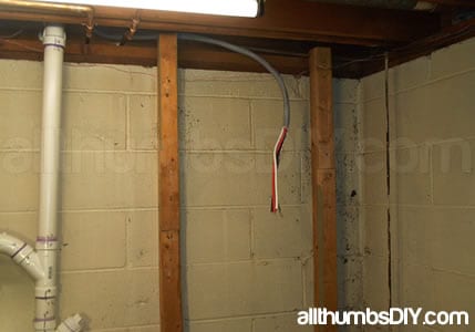
Installing a New Subpanel is a multi-part series article, broken into Part 1, Part 2, Part 3, Part 4 and Part 5.
PREP WORK
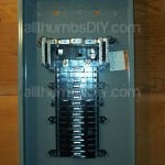
My Square D QO Series Value Pack sub panel included the following items:
- Main Box
- Panel cover
- Five Circuit Breakers (in a small box)
- Green Screw (ground bonding)
- Main breaker (pre-installed)
- Installation Manual
Step 1 – Isolating neutral and ground
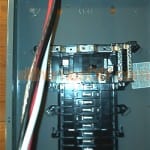
Because the Square D panel came with neutral and ground isolated from each other (as required for sub panel use), I immediately threw out the green (ground bonding) screw (fig.3.1).
Why isolate only in the subpanel? Here is one of the best answers I’ve seen:
Because if I bond the neutral and ground at the sub panel, then stray currents from the neutral return could go through the equipment ground on the electrical devices fed from the sub panel. If you isolate the neutral and ground at the sub panel, then any currents would go to the service ground at the main panel. – By Asker at Yahoo Answers<
For that reason, the main panel is the only place where the neutral and equipment ground should be bonded.
Step 2 – Install ground bus bars
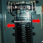
First, I lay down the panel on a clean, flat surface then unpacked two ground bus bar kits. These kits come with 2 screws but I found out that I only needed one screw per each bus bar. Looking at the middle section of either sides, I located small screw holes (click here) then installed the ground bus bars by sliding them against the panel’s bumps using 30 lb/ft torque screwdriver. (fig.3.2 and fig.3.3)
Step 3 – Remove panel knockout then Install NM connector for the main cable
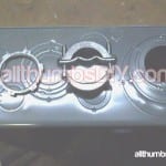
I carefully punched out the knockout concentric ring (2nd inner ring) using a flat-head screwdriver and hammer (fig.3.4).
I needed to be extra careful because if I hammered it with too much force, I could have knocked out the larger rings (which would have meant I needed to go out and buy a larger sized NM connector)
Step 4 – Cable routing
As previously stated, I chose the basement location directly under kitchen. That meant I had to:
- Run the cable up from the main panel in the garage ceiling
- Run the cable across the garage attic space
- Drop the cable in the wall between the mudroom and kitchen
- Make a ¾” hole on the sole-plate then fish the wire through
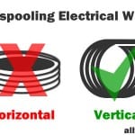
TIP: When un-spooling a wire DO NOT lay down the wire flat on the ground – they will kink as you start to un-spool. Instead, keep the spool vertical – think how toilet paper unrolls from the holder
So, I un-spooled and straightened my cable in the garage then I carefully cut a hole in the ceiling (directly above the main panel). I then inserted the cable and because I was working alone, I made multiple trips back and forth to feed the cable into garage attic space. Because the aluminum cable was fairly light, I was able to work alone. If I was working with a copper cable, I would definitely have recruited one of my friends to help me.
Finally, I carefully routed the cable along the floor joists, making sure that it did not come in contact with any sharp objects, then dropped it between the wall cavity to the basement location.
I left approximately 10 feet of cable hanging in front of the subpanel location to make sure that I had some “extra” to play with when attempting to connect the cable to the sub panel.
Step 5 – Install mounting studs
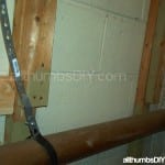
Because my mounting location had 2×2 braces already attached to a basement wall, all I had to do was simple screw in additional 2×2 pieces using 1.5″ Deckmate screws to create about 4-5 inches of clearance space (I will tell you why I did this in the later section).
Step 6 – Install mounting backboards (temporary)
Because I decided to surface-mount my sub panel (much easier to add additional circuits later), I attached two backboard pieces (made of plywood) to the mounting studs. I used 4ft level to ensure that both pieces were plumbed and leveled.
Step 7 – Install sub panel (temporary)
Using a magnetic torpedo level, I surface mounted the sub panel. I centered the panel by measuring the distance between the edge of the backboard. I left approximately 3 feet of space on the top to make sure that I had enough room to insert the cable into the panel
Step 8 – Deconstruction
Now that I was sure that everything fit perfectly, I had to disassemble everything so that I can paint the backboard with a black paint. Black paint was required in my jurisdiction because I was told that in case of a fire, the black paint would retard the fire spread. Not sure if this was more of a myth or not, but rather than arguing, I decided to paint my backboards (besides, it would look nice!)
After I unscrewed and remove the panel from the backboard, I took at 3/8″ drill bit and enlarged the screw holes so that I can use a larger lag bolts during final assembly.
Step 9 – Paint & Re-assembly
I applied 2 coats of black paint to dry over-night. After making sure that they were dry next morning, I removed the bottom backboard piece. This step was necessary for me to reach behind the top backboard piece to install washers & nuts for the lag bolts. It was bit awkward at first, but with no one else helping me, I was able to securely attach the top 2 bolts first, re-attach the bottom backboard piece, then finally my last 2 lag bolts and washers in about 20 minutes.
NEXT >> Installing a new Subpanel – Part 5
RELATED ARTICLES
- Installing a new Subpanel – Part 1
- Installing a new Subpanel – Part 2
- Installing a new Subpanel – Part 3
- Installing a new Subpanel – Part 4
- Installing a new Subpanel – Part 5

David
Friday 8th of July 2016
Hello, I found a couple errors in your description about isolation.
1. "Because the Square D panel came with neutral and ground isolated from each other (as required for sub panel use), I immediately threw out the green (ground bonding) screw "
Neutral & ground are not isolated. They are bonded. See the 4 bus bars? Two outer are ground & two inner are neutral. In factory configuration they are bonded. 2. To isolate, Remove the two outer ones and install where you added your kit. You will notice two holes in box align perfectly with the bus bar. 3. Green screw, You were correct not to use but your description was incorrect.. "came with neutral and ground isolated from each other (as required for sub panel use)" You use this screw to ground box if used as main panel, don't use if sub panel.
Installing a new Subpanel – Part 1
Monday 16th of July 2012
[...] Installing a new Subpanel – Part 4 [...]
Installing a New Subpanel – Part 5
Sunday 15th of July 2012
[...] Installing a new Subpanel – Part 4 [...]
Installing a New Subpanel – Part 2
Saturday 14th of July 2012
[...] Installing a new Subpanel – Part 4 [...]
Installing a New Subpanel – Part 3
Saturday 14th of July 2012
[...] Installing a new Subpanel – Part 4 [...]